Dimension Catalyst Ex Software Download
CatalystEX for Bit is a Shareware software in the category Miscellaneous developed by Dimension Printing. The latest version of CatalystEX for Bit is currently unknown. It was initially added to our database on. CatalystEX for Bit runs on the following operating systems: Windows. CatalystEX for Bit has not been rated by our users yet. In this section, you can find technical resources and service documentation for legacy PolyJet printers no longer offered for sale. The End of Support dates for discontinued products are listed below. Built on enhanced Polaris architecture, Radeon™ RX 580 graphics card with 8GB GDDR5 memory delivers incredible VR and gaming experience. See more at AMD.com!
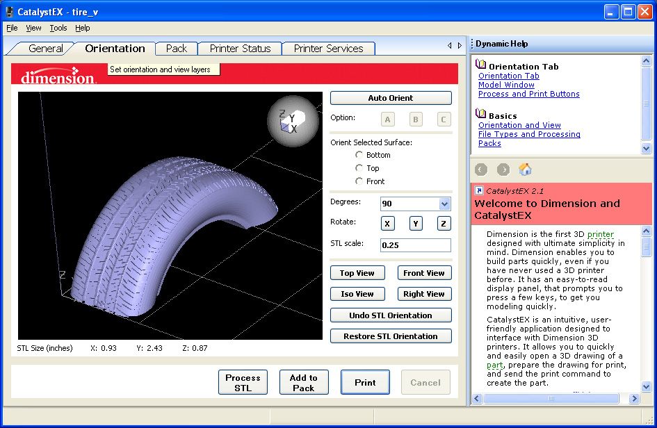
CatalystEX allows you to take full control of how to build your part. The Properties window is accessed from the General Tab.

Layer resolution – height of each layer of material extruded to produce a part. Available resolutions are based on printer type.007 inch (.178 mm) Elite Only.010 inch (.254 mm) Elite, 1200, and uPrint.013 inch (.330 mm) 1200 Only Resolution will effect build time and surface finish – A shorter height creates a smoother finish, but will take longer to build. Model interior – establishes type of fill used for interior, solid areas of the part.
Solid – used when a stronger, more durable part is desirable. Build times will be longer and more material will be used. Sparse – high density (Elite, 1200es, uPrint 3D Printers only) – this is the default model interior style and it is highly recommended. Build times will be shorter, less material will be used, and the possibility of part curl for geometries with large mass will be greatly reduced.
Sparse -low density- the interior will be “honeycombed/hatched”. This style allows for the shortest build times and lowest material use. Support fill – support material is used to brace the model material during the build process. It is removed when the part is complete. Support fill options will affect the support strength and build time of the print. Basic – may be used for most parts. It uses a consistent spacing between the support raster tool paths.
Sparse – minimizes the amount of support material. Sparse uses a much larger spacing between raster tool paths than basic supports. Minimal – is used for small parts that have small features in need of supports. It is designed to make support removal easier on these small parts. Do NOT use minimal supports on large parts or parts with tall columns of support.
Break-away – similar to sparse supports without a closed tool path-perimeter curve. They are easier to remove than other support styles but build slower than sparse supports (not available for all printers). Surround – the entire model is surrounded by support material. Typically used for tall, thin (narrow) models (e.g., pencil). Number of copies – select the number of copies you want to Print or Add to Pack. The number of possible copies will be limited by the size of the modeling platform. Multiple copies sent to Print will first be saved as a Pack.cmb file.

If using the Add to Pack button, each click will send the same number of copies to a Pack – if space allows. From the Pack Tab you can view the arrangement of the part(s) on the Modeling Platform.
STL units – select ‘inches’ or ‘millimeters’ units of measure for your STL file. STL files do not specify units of measure. You need to specify the units as either inches or millimeters. Example: An STL file of a cube designed with a dimension of 100 X 100 X 100, opening with a unit of measure set to inches, will not fit within the build envelope. By changing the units of measure to ‘millimeters’, the part will be resized – and fit within the envelope.
STL scale – before you process a part for printing, you can change the size of the part within the build envelope. Every part has a pre-defined size within the STL file. After you have opened the file you can change the size of the part produced from the STL file by changing the scale. The Scale always relates to the ORIGINAL (or “Save As”) STL file size definition.
Insight FDM driver software is supposed to be used only with the Stratasys Fortus production level systems but can also be used to get the most out of the professional level Dimension 3D printers. CatalystEX, the official driver software for Dimension machines, is very dumbed down compared to Insight.
Insight gives you much more control of your Dimension printer. Some of the capabilities of Insight are: Variable density parts (decrease time and material consumption) Control seam locations on vertical walls (better part aesthetics) Automatically thicken details too thin for the tool path width Custom tool paths for thin walls and bosses This short instruction document covers how to install Insight to work with Dimension printers. Control Center also installs along with Insight and can be used to create packs, send part build commands and better manage the print queue. A few tips on starting to use Insight are included as well as the link to best practices documents.

After installation, you can still use CatalystEX if you prefer for simpler prints. Insight and CatalystEX can be used interchangeably on the same computer. How to use Fortus Insight FDM driver to rev up Dimension 3D printers too. 1.
Preface Insight FDM driver software is supposed to be used only with the Stratasys Fortus production level systems but can also be used to get the most out of the professional level Dimension 3D printers. CatalystEX, the official driver software for Dimension machines, is very dumbed down compared to Insight. Insight gives you much more control of your Dimension printer. Some of the capabilities of Insight are: Variable density parts (decrease time and material consumption) Control seam locations on vertical walls (better part aesthetics) Automatically thicken details too thin for the tool path width Custom tool paths for thin walls and bosses This short instruction document covers how to install Insight to work with Dimension printers.
Control Center also installs along with Insight and can be used to create packs, send part build commands and better manage the print queue. A few tips on starting to use Insight are included as well as the link to best practices documents.
After installation, you can still use CatalystEX if you prefer for simpler prints. Insight and CatalystEX can be used interchangeably on the same computer. How to install Insight to work with Dimension printers.You may need the admin login not just to install but also to copy and replace files on the computer’s C drive Program Files folder. 1. Install CatalystEX if not already. Install Insight.
(If you ask a Fortus user nicely they might give you the install files. Many AMUG people have them.) There are two install file folders (InSight & x64). Copy C:Program FilesDimensionCatalystEX 4.5guimodelerSetup.tcl to C:Program FilesStratasysInsight 10.6gui (Replace the original modelerSetup.tcl.) 4. Copy C:Program FilesDimensionCatalystEX 4.5modelers to C:Program FilesStratasysInsight 10.6modelers (Copy the contents of the CatalystEX 'modelers' folder to the Insight 'modelers' folder.). 5. Start Insight software and choose your printer.
Dimension Catalyst Ex Software Download Free
Modeler Setup on the right side should have a small icon of a Dimension printer. Click on it to get Configure Modeler window where you can pull down menu on Modeler Type and choose SST 1200es or other Dimension machine model. Model material should be ABS P430, color doesn't matter, and Support material should be ABS-P400SR. Slice height 0.01'. One of the many benefits of using Insight over CatalystEX just in regards to quality checking your build files is that you can slice the model first before generating the support structures and the toolpaths in separate steps. “Slice with Wall Thickness Filter” option in particular is good for detailed architectural model files which might have embossed features that would otherwise be too thin for a toolpath to be generated.
It will automatically tweak those details so they will be wide enough to get a toolpath and not be left off of the printed model. Another tip is that when inspecting the tool paths by stepping through the layers, Shade toolpaths is a good option for better viewing. (Right click menu, or Toolpaths menu.) Fifteen documents from Stratasys on using Insight are here:.
6. To get Insight updates when prompted, try using serial number P15237 which was a Fortus unit under service contract as of October 2016. The few other fields in the pop-up form don’t matter. The program files will likely need to be moved again per above. Or just keep using the version currently installed. FDM Control Center Control Center also installs along with Insight. It is similar to the Pack Tab in Catalyst but also has enhanced features.
After you are satisfied with quality checking and tweaking your file in Insight, Save as Toolpath (.cmb file). Then Insert CMB in Control Center. Multiple CMB’s can be imported for a nested cycle. The usual machine time and material consumption data is here as well as a handy calendar view of the queue. Or just use CatalystEX's Pack Tab to Insert CMB. Additional Note: CMB View (another way to view tool paths) By the way, if you prefer to use simpler standalone software for QC of the CMB file toolpaths by stepping through the layers then use CMB View. CMB View is already installed along with CatalystEX.
You just have to click on cmbview.exe in C:Program FilesDimensionCatalystEX 4.5nt Drag it onto the desktop for easy access.